
Development of Shaft Strength Calculation Macro in Microsoft Excel: A Practical Guide for Engineering Students
Development of Shaft Strength Calculation Macro in Microsoft Excel: A Practical Guide for Engineering Students
*Joel M. Infornon., Rey Joseph C. Capilitan., Julius O. Paler., Rommel T. Valmoria., Khesiya Mae C. Manlangit., Jerome T. Bongato., Dave Raymond. Boterez., Hilarion Arong Jr
Faculty of Engineering, Department of Mechanical Engineering, Southern Leyte State University San Roque, Sogod, Southern Leyte, 6606 Philippines
Publication Information
Journal Title: International Journal of Research and Scientific Innovation (IJRSI)
Author(s):Joel M. Infornon., Rey Joseph C. Capilitan., Julius O. Paler., Rommel T. Valmoria., Khesiya Mae C. Manlangit., Jerome T. Bongato., Dave Raymond. Boterez., Hilarion Arong Jr
Published On: 06/18/2025
Volume: 12
Issue: 3
First Page: 618
Last Page: 634
ISSN: 2321-2705
Cite this Article Joel M. Infornon., Rey Joseph C. Capilitan., Julius O. Paler., Rommel T. Valmoria., Khesiya Mae C. Manlangit., Jerome T. Bongato., Dave Raymond. Boterez., Hilarion Arong Jr ;Development of Shaft Strength Calculation Macro in Microsoft Excel: A Practical Guide for Engineering Students,Volume 12 Issue 3, International Journal of Research and Scientific Innovation (IJRSI), 618-634, Published on 06/18/2025, Available at https://rsisinternational.org/journals/ijrsi/articles/development-of-shaft-strength-calculation-macro-in-microsoft-excel-a-practical-guide-for-engineering-students/
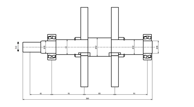
In the field of mechanical engineering, shaft strength calculations are crucial for creating reliable and efficient machinery. Traditionally, these calculations are done manually, a process that can be time-consuming and prone to mistakes, which can lead to design issues. To address these challenges, a practical guide is available to help engineering students develop a gear calculation macro in Microsoft Excel, transforming a complex and error-prone task into a streamlined, automated one. The guide begins by providing a solid understanding of fundamental gear mechanics concepts, ensuring that students are well-versed in the principles before diving into Excel’s technical aspects. The analyzed shaft, manufactured from S45C steel, is a keyed shaft designed to handle a bending moment of 502.8 N·m and an output torque of 260 N·m, with no thrust load (Fa = 0 N). The shaft has a diameter of 28 mm and a stepped section with a maximum diameter of 35 mm, including a radial dimension of 3.5 mm for smooth transition. A keyway of 8 mm width and 4 mm depth is machined to ensure effective torque transmission. The material’s tensile strength is 686 N/mm², with a factor of safety (SF) of 1 applied to the design. The fatigue stress connection factor for the keyway is calculated as 0.7857, reflecting the stress concentration induced by the keyway geometry. A size factor of 0.9357 accounts for the shaft’s dimensions. Fatigue stress reduction factors for bending (βm = 1.5909) and torsion (βt = 1.1863) are computed based on material properties, surface finish (m = 1), and geometric considerations such as the step radius and shaft diameter. The equivalent shear stress on the shaft is 211.9 N/mm², below the allowable stress limit of 300 N/mm², resulting in a safety factor of 1.42 under fatigue loading. The shaft also satisfies yield criteria, with a safety factor of 1.18 compared to the material’s yield strength of 250 N/mm². This analysis confirms that the shaft is structurally sound and can reliably withstand the applied bending and torsional loads, ensuring safety and durability in its application. Its design effectively balances strength, material utilization, and performance requirements.
Keywords: Excel macro, Steppe shaft, Factor of safety, Equivalent shear stress, Durability
Copyright © 2023 Gyaanarth.com